


Engelfried Maschinentechnik GmbH
Tel.: +49 (7361) 9866-0
| Détails de l'offre | |
| Numéro d’entrepôt | 1305-6935 |
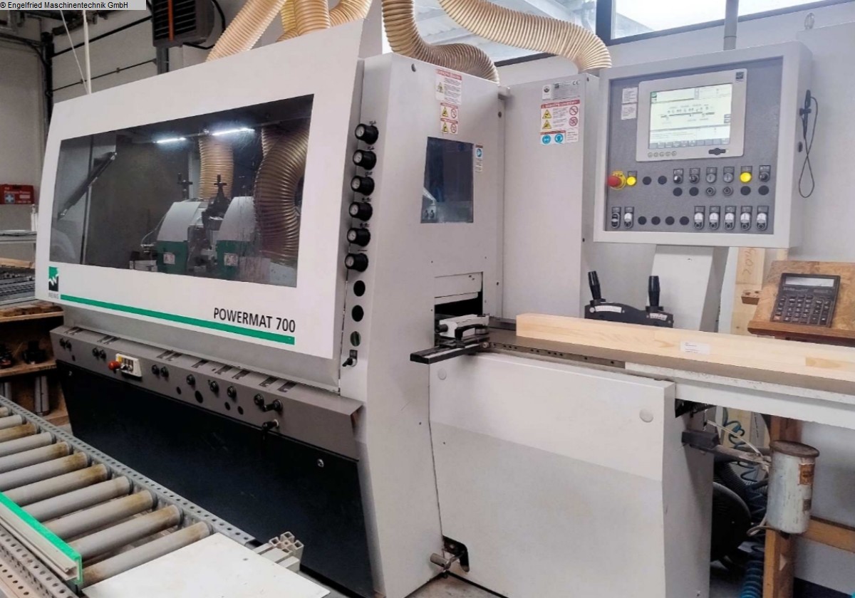
| Type de machine | Moulurière 4 faces |
| Marque | WEINIG |
| Modèle | Powermat 700 |
| Année de construction | 2017 |
| Type de commande | konventionell |
| Lieu d’entreposage | Deutschland |
| Pays d’origine | Allemagne |
| Délai de livraison | 8 Wochen |
| Base de fret | ab Standort |
| Nombre des broches | 6 St. |
| Largeur de travail | 20-230 mm |
| Hauteur de rabot | 10-160 mm |
| Longueur de la table | 2500 mm |
| Moteur d'avancement | 7 kW |
| Vitesse d'avancement | max. 40 m/min. |
| Poids de la machine | 3500 kg |
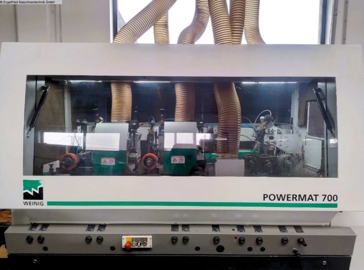
Weinig Powermat 700
------------------------------------------------
Brief summary Manufacturer's description:
Working width: 230 mm
Working height: 160 mm
Spindle arrangement:
Bottom: 2 pieces
Right: 1 piece
Left: 1 piece
Top: 2 pieces
8,000 rpm
5 x HSK/Powerlock
Window package with glazing bead separation
Axial and radial CNC-controlled spindles
Large PowerCom Plus control unit with touchscreen
Detailed description:
-----------------------------------------------
Technical data:
-------------------------
Working width 20 - 230 mm (with mould flight circle 93 - 125 mm)
Working height 10 - 160 mm (for tool flight circle 93 - 125 mm)
1st spindle
------------------------------
First lower horizontal spindle
Motor 7.5 KW
Diameter 40 mm
Speed 6,000 rpm
Tool flight circle 125 - 145 mm
Tool groove circle rebate cutter 130-160 mm
Axial adjustment range 17 mm
Rebating device, including rebate cutter
MarathonCoating in front of 1st lower spindle
2. tool holder POWERLOCK/HSK
------------------------------
First right-hand tool holder
Motor, together with left vertical spindle 15 KW
Speed 8,000 rpm
Including high-performance ball bearing
Tool flight circle 40 mm below table level 93 - 200 mm
Tool flight circle 80 mm below table level 93 - 180 mm
Tool flight circle for straight cutterheads max. 180 mm
Maximum moulding depth 35 mm
Axial adjustment travel for PowerLock 55 mm
Translated with DeepL.com (free version)
Max. Tool diameter behind stop plane 180 mm
Right-hand spindle controlled axially by motor (55 mm),
Shortened roller distance compared to the right-hand spindle, designed for a saw diameter of
Sawing diameter of 180 mm on the right-hand spindle (centre distance 141 mm).
Second feed roller can be quickly adjusted axially.
Axial CNC-controlled quick adjustment and positioning of the tool holder
tool holder in conjunction with memory function or PowerCom
Radial CNC - controlled - quick adjustment and positioning of the tool holder
tool holder in conjunction with memory function or PowerCom
3. tool holder POWERLOCK/HSK
------------------------------
First left tool holder
Shared motor with 1st right vertical spindle
Speed 8,000 rpm
Including high-performance ball bearing
Tool flight circle 40 mm below table level 93 - 200 mm
Tool flight circle 80 mm below table level 93 - 180 mm
Tool flight circle for straight cutterheads max. 180 mm
Maximum moulding depth 35 mm
Axial adjustment travel for PowerLock 55 mm
Two lateral pressure rollers in front of the left spindle, travelling and spring-mounted
Adjustment path of the feed rollers in relation to the left-hand spindle, axial 35 mm
Extension of the pendulum axis compared to the left-hand spindles to 150 mm
Axial CNC-controlled quick adjustment and positioning of the tool holder
tool holder in conjunction with memory function or PowerCom
Radial CNC - controlled - quick adjustment and positioning of the tool holder
tool holder in conjunction with memory function or PowerCom
Translated with DeepL.com (free version)
4. tool holder POWERLOCK/HSK
------------------------------
First upper tool holder
Motor 7.5 KW
Speed 8,000 rpm
Including high-performance ball bearing
Tool flight circle 93 - 200 mm
Tool flight circle for straight cutterheads max. 180 mm
Maximum moulding depth 35 mm
Axial adjustment travel 40 mm
Split pressure shoe in front of upper spindle with horizontal adjustment plane,
Adjustable to tool flight circle and swivelling away from the tool, pneumatic
Pressure shoe before and after the upper spindle with electronic digital displays
digital displays, integrated in the memory function or the PowerCom
Axial CNC-controlled quick adjustment and positioning of the tool holder
tool holder in conjunction with memory function or PowerCom
Radial CNC - controlled - quick adjustment and positioning of the tool holder
tool holder in conjunction with the memory function or PowerCom
Translated with DeepL.com (free version)
5. tool holder POWERLOCK/HSK
------------------------------
Second upper tool holder
Motor with brake 7.5 KW
Speed 8,000 rpm
Including high-performance ball bearing
Tool flight circle 93 - 200 mm
Tool flight circle for straight cutterheads max. 180 mm
Maximum moulding depth 35 mm
Axial adjustment travel 40 mm
Split pressure shoe in front of upper spindle with horizontal adjustment plane,
Adjustable to tool flight circle and swivelling away from the tool, pneumatic
Pressure in front of the 2nd upper spindle with flat infeed bevel
(2 mm lift-out) laterally displaceable, incl. monitoring sensors to prevent incorrect operation.
incorrect operation. Pressure elements before and after the 2nd upper spindle with
quick adjustment for mould change via handwheel.
Pressure shoe before and after the upper spindle with electronic digital displays
digital displays, integrated in the memory function or the PowerCom.
Glazing bead removal after 2nd upper spindle, pneumatically controlled forwards/backwards.
Pressure elements, discharge and extraction bonnet are designed for a saw
planing head combination with tool flight circle 180 mm/125 mm, incl.
monitoring sensor to prevent incorrect operation and a pressure roller for
holding down the glazing bead.
Axial CNC - controlled - quick adjustment and positioning of the tool holder
tool holder in conjunction with memory function or PowerCom
Radial CNC - controlled - quick adjustment and positioning of the tool holder
tool holder in conjunction with memory function or PowerCom
6. tool holder POWERLOCK/HSK
------------------------------
Second lower tool holder
Motor with brake 7.5 KW
Speed 8,000 rpm
Including high-performance ball bearing
Tool flight circle 93 - 200 mm
Maximum moulding depth 15 mm
Axial adjustment range 40 mm
Sawing (only in conjunction with wood insert):
Max. saw cutting height (saw Ø 200 mm, flange Ø 100 mm) 40 mm
Max. cutting height (saw Ø 200 mm, flange Ø 90 mm) 45 mm
Axial CNC-controlled quick adjustment and positioning of the tool holder
tool holder in conjunction with memory function or PowerCom
Radial CNC - controlled - quick adjustment and positioning of the tool holder
tool holder in conjunction with memory function or PowerCom
Spindles in general
------------------------------
All tool holders with high concentricity.
Conventional tools can be used in steel design
with max. tool flight circle 125 mm up to a working width of
working width of 230 mm
(maximum tool weight 22 kg - incl. rebate milling cutter)
up to a speed of 8000 rpm can be used.
Important: Ensure high tool quality in terms of balance quality, axial and radial run-out tolerance.
tolerance.
Optimised chip flow thanks to improved flow technology on the extraction hoods
Feed system
------------------------------
Electronic feed incl. brake, infinitely variable 5 - 40 m/min.
Motor 7 kW
Feed roller in front of 1st lower tool pneumatically controlled high-low
All feed rollers with quick adjustment
Durofer pointed-tooth rollers with depth limiter and self-cleaning
CNC-controlled adjustment and positioning of the feed up/down
in conjunction with the memory function or PowerCom.
Machine electrics
------------------------------
Operating voltage 400 Volt (voltage range 380 x 420 Volt), 50 Hz
All spindle motors in IE 3 design
Machine stand, table and stops
------------------------------
Dressing table 2.5 m long (incl. joining ruler)
Side pressure roller on infeed table, spring-mounted
MarathonCoating for machine table and stops
(without infeed table and special table tops).
Special coating to protect the table tops and stops from excessive wear.
wear. For the processing of abrasive materials
(e.g. tropical woods, MDF, chipboard).
The stops after the right-hand spindle are set to 35 mm except for the
square moulding cut-out (designed up to IV90). The stop after the
2. upper spindle is intended for the use of an L-shaped support bar.
A driven rubber roller in the outfeed table, or in front of the universal spindle
(if available), spring-loaded 50 mm wide
Air cushion system in the machine table, 2 separate air circuits via pendulum shafts
controlled
Pressure elements and guides
------------------------------
Guiding ruler running along the left-hand spindle, 7 mm thick and with pneumatic
clamping in the machine run-out. The edges of the ruler are radiused to avoid scoring the workpiece.
edges of the ruler are provided with radii.
Machine operation: PowerCom Plus control:
------------------------------
Profile and tool data management software
The set values can be calculated or saved.
These are shown on the dual digital displays.
Touchscreen function for graphically supported operation of the machine
10,000 profile and tool memory locations each
Profile images can be stored in the profile data
ServiceControl software for maintenance support
Integrated network card for connection to OptiControl or other PCs
USB stick for manual data backup
Operating and machine data acquisition, incl. length counter
User administration with password function
Logging of production interruptions
CNC-controlled adjustment and positioning of the feed up/down in conjunction with
connection with PowerCom
Lubrication points for axial spindle adjustment
Centralised position of lubrication points at the front of the machine
Safety and noise protection
------------------------------
Machine including spindle brakes
Full safety panelling
Easily liftable safety bonnet with window covers the entire
covers the entire working area and protects against mechanical
mechanical hazards.
When the safety bonnet is raised, the tool holders and feed are
and feed are automatically switched off.
With the CE version, it is not possible to open the safety bonnet during
opening the safety hood during automatic operation is not possible.
Electromagnetic locking of the safety hood
(only after the tools have come to a standstill, approx. 15 sec,
the bonnet can be opened)
Interior lights in the safety bonnet
Machine without machining tools.
------------------------------------------------
Price of the above machine and optional tools on request!
------------------------------------------------
(Technical data according to manufacturer - without guarantee!)


 Retour
 Imprimer